
Table of Contents
EARTH GROUND TESTING
A grounding system is only effective if it can actually discharge electrical energy into the soil. Earth ground testing is used to evaluate this performance by measuring how easily current flows from the grounding system into the earth.
In electrical networks across Dubai and the UAE, grounding is not just a design requirement — it is a critical safety function. Whether it’s a fault current, leakage current, or lightning surge, all of it depends on a reliable path to earth.
What We Check During Testing
Instead of looking at grounding as a single value, the test focuses on overall performance of the system in real conditions:
- Resistance between electrode and soil
- Continuity of grounding conductors
- Effectiveness of multiple interconnected electrodes
- Influence of soil condition on grounding performance
- Ability to safely dissipate fault and surge currents
This gives a more practical understanding of whether the system will perform when required.
Why Grounding Performance Changes Over Time
Grounding systems do not remain constant after installation. In UAE conditions, several factors can affect performance:
- Dry or sandy soil increasing resistance
- Corrosion of earth rods and connections
- Construction changes affecting soil composition
- Loose or damaged grounding connections
- Changes in moisture levels due to cyclic seasons
Because of the mentioned points, a grounding system that was once effective may gradually become unreliable without any visible signs.
Earth Testing Methods Used on Site
Different sites require different approaches. The method is selected based on access, system design, and operational constraints.
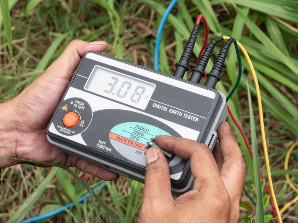
- FALL-OF-POTENTIAL METHOD
Used where space is available. Provides accurate measurement using auxiliary probes placed in the soil.
Test Setup
The earth electrode to be tested is identified and, where possible, temporarily isolated to avoid parallel earth paths affecting the reading.
Placement of Test Probes
Two auxiliary spikes are driven into the ground in a straight line:
- One acts as a current electrode placed at a distance (typically around 20 meters or more depending on site conditions)
- The second acts as a potential electrode, placed between the main electrode and the current probe
Injection of Test Current
The earth tester injects a known current into the soil through the current electrode. This simulates how fault current would flow into the ground.
Reading measurement and Verification
Then the ground tester will give measured resistance values based on Ohms law. Readings are then recorded. Also, to ensure accuracy what we do is, the potential probe is moved slightly and readings are taken again. Stable values confirm correct measurement, while variation indicates improper spacing or soil influence.
- CLAMP-ON METHOD
Used in live systems where disconnection is not feasible. Measures loop resistance of interconnected grounding paths.
Test Setup
- A clamp-type earth tester is placed around the earth conductor or electrode
- The instrument induces a test signal and measures the loop resistance of the grounding path
- No auxiliary probes or electrode isolation are required
- It measures the overall loop resistance and may not represent a single electrode value if multiple parallel paths exist.
Selective Testing
Applied in complex systems to isolate and evaluate specific electrodes without complete shutdown. Based on your site conditions and earthing systems we can help you to find the best method for earth ground testing. Also, each method is chosen to balance accuracy, safety, and site practicality.
Acceptance Criteria in UAE
There is no single fixed threshold value for all installations. For critical installations (data centers, substations, sensitive systems), earth resistance is typically maintained at 1 ohm or less, as commonly followed in Dubai projects in line with Dubai Electricity and Water Authority practices. In many cases, achieving 1 ohm is considered as a best-practice target.
However, the actual acceptable value may vary depending on site conditions, soil conditions, system design, and the according authority specifications.
Where Ground Testing Becomes Critical
Grounding performance is especially important in:
- Industrial facilities with heavy electrical loads
- Commercial buildings and high-rise structures
- Data centers and sensitive electronic environments
- Substations and distribution networks
- Lightning protection systems
In these installations, poor grounding can directly impact safety, equipment reliability, and system stability.
Practical Field Considerations in UAE
Testing grounding systems in UAE requires more than standard procedures. Site conditions often introduce challenges such as:
- Limited space for probe placement in urban areas
- High soil resistivity in dry regions
- Multiple parallel earth paths affecting readings
- Continuous operation where shutdown is not possible
We focus on adapting the best test method to suit such conditions while maintaining accuracy and safety.
Outcome of the Test
The results are not just numbers — they provide insight into system condition:
- Whether grounding resistance is within acceptable range
- Identification of weak or deteriorating electrodes
- Need for additional rods or system enhancement
- Risks associated with poor fault current dissipation
Recommendations are based on practical improvements that can be implemented on site.
FAQs – Earth Ground Testing
- Why is low earth resistance value important?
It ensures fault and surge currents are safely discharged without affecting equipment or people. - Can testing be done without disconnecting the system?
Yes, clamp-on and selective methods allow testing in many live systems. - What affects grounding resistance the most?
Soil condition, moisture content, and electrode condition are major factors. - Is one earth electrode enough?
In many cases, multiple electrodes are used to achieve lower resistance. - When should grounding be tested?
During installation, after modifications, and periodically during maintenance.